
- Ideas are our core competence
- +49 7723/925-0
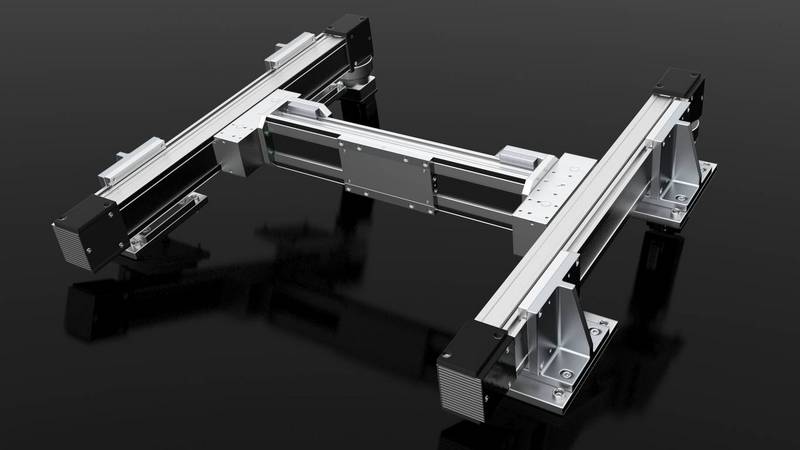
Positioning system H-portal
- Product type: Linear drives
- Download
- CAD data: Positioning system H-portal
- CAD data: Levelling elements
- Operating instructions
-
Generel details
-
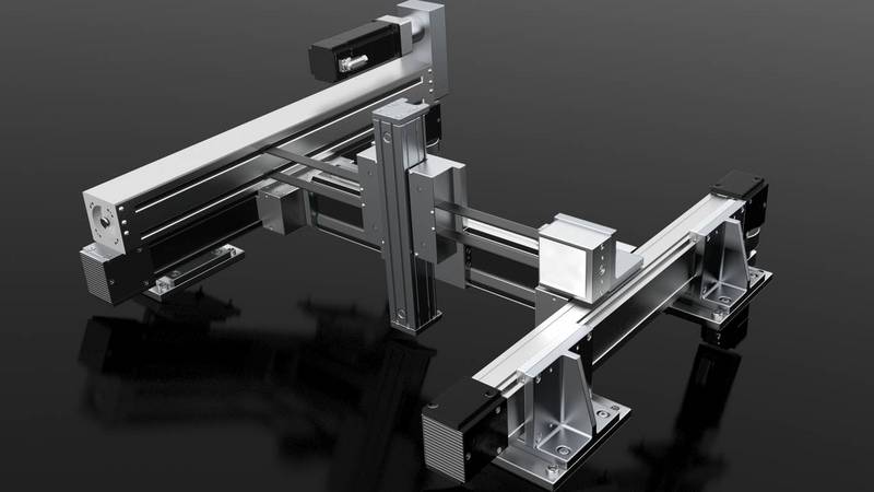
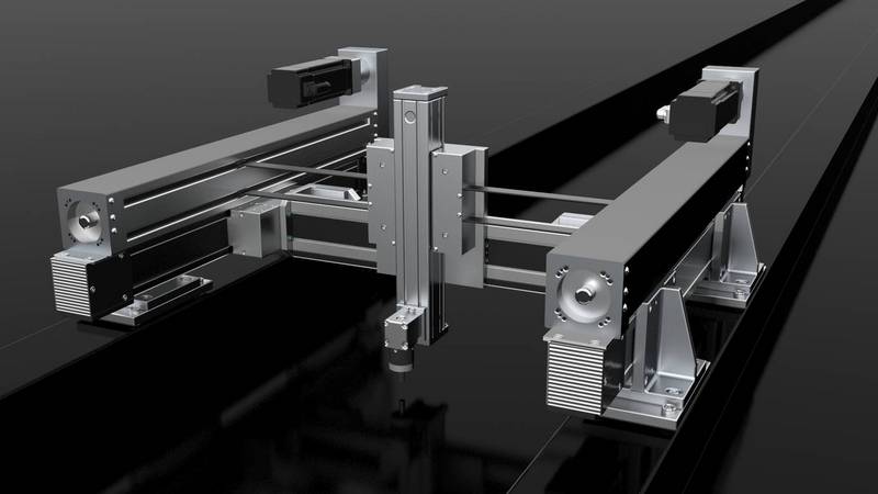
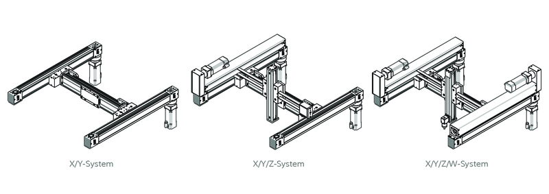
There are 3 different expansion stages of the H-portal
- X/Y-System
The X/Y system is based on the proven linear units Module 80/15 and Module 115/42 or Module 115/42 B. They form the base of the H-Portal.
- X/Y/Z-System
The X/Y/Z system can be expanded to a gantry with the linear unit Module 60/33.
- X/Y/Z/W-System
An optional turning unit at the Z-axis is available for demanding positioning tasks.
- X/Y-System
-
Description of function
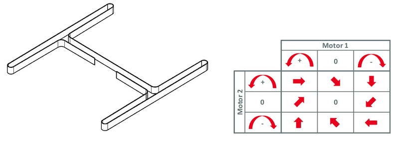
The belt in the X/Y-system is arranged in an H-shape. The movements in X and Y-direction are realised by one belt. The belt is fixed at the slide of the Y-axis. The drive takes place at one of the 180°-deflections at the X-axis. For a drive in X-direction, both motors have to be turned exactly oppositely, in Y-direction both
motors have to be turned synchronously. If one motor stands still, the system drives under 45°. The movements of X and Y are therefore dependent on both motors. -
Technical details
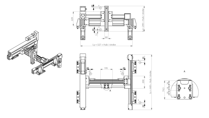
stroke X (stroke increments 75 mm) 100 - 1525 mm stroke Y (stroke increments 60 mm) 100 - 700 mm stroke Z (stroke increments 40 mm) 110 - 550 mm weight X/Y/Z system approx. 50 kg moved mass X/Y/Z system in X/Y/Z direction 30 / 13.5 / 5 kg moved mass X/Y system in X/Y direction 21 / 4.5 kg weight increase per 100 mm stroke Y-axis 0.95 kg weight increase per 100 mm stroke Z-axis 0.6 kg recommended handling weight 4 kg repeat accuracy +/- 0.05 mm infeed constant without gear X/Y 140 mm / turn infeed constant without gear Z 160 mm / turn recommended size servo motor AM8032 -
Features
-
Accessories: Clamping elements
-
Accessories: Levelling elements
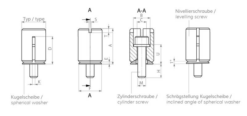
These elements are ideal for the levelling of assembly surfaces which cannot be mechanically processed or only with great effort. You can find more information and helpful tutorials here.
-
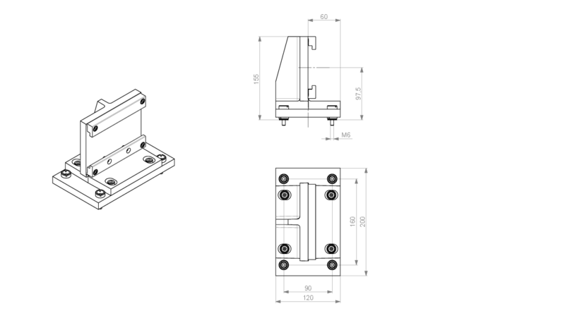
Accessories: Mounting angle with levelling plate

We support our customers
Advice, catalogues & more
Do you have questions? Initial concept ideas? Or would you like us to look at a problem on site?
Contact us and let us advise you without obligation - on site or by phone, video call or email. Our sales team will be happy to get in touch with you and advise you on your handling task.
We look forward to hearing from you!


